MIL-DTL-83413/7E
Inches
mm
Inches
mm
Inches
mm
.003
0.08
.113
2.87
.75
19.1
.004
0.10
.125
3.18
.84
21.3
.010
0.25
.130
3.30
.88
22.4
.031
0.79
.130
3.30
1.25
31.4
.062
1.57
.203
5.16
1.50
38.1
.078
1.98
.205
6.35
2.80
76.1
.080
2.03
.380
9.70
3.20
81.3
.090
2.29
.500
12.70
4.13
104.9
NOTES:
1. Dimensions are in inches.
2. Metric equivalents are given for information only.
3. Surface toughness: If cast, smooth cast finish 125 or 250 all over, except machine surface 63.
4. Remove all burrs and sharp edges .010 (0.25 mm) to .020 (0.51 mm) radius.
5. Unless otherwise specified, tolerance is ±.03 (0.8 mm) on decimals and ± 1° on angles.
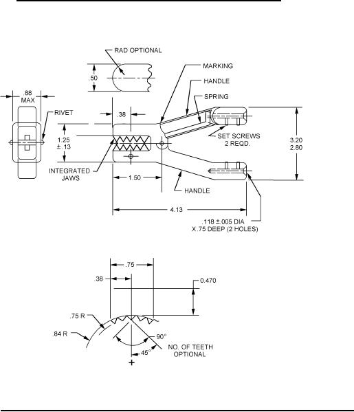
FIGURE 1. Grounding clamp, for types I and III grounding assemblies - Continued.
FIGURE 2. Grounding clamp, for types I and III grounding assemblies with integrated jaw.
2
For Parts Inquires call Parts Hangar, Inc (727) 493-0744
© Copyright 2015 Integrated Publishing, Inc.
A Service Disabled Veteran Owned Small Business