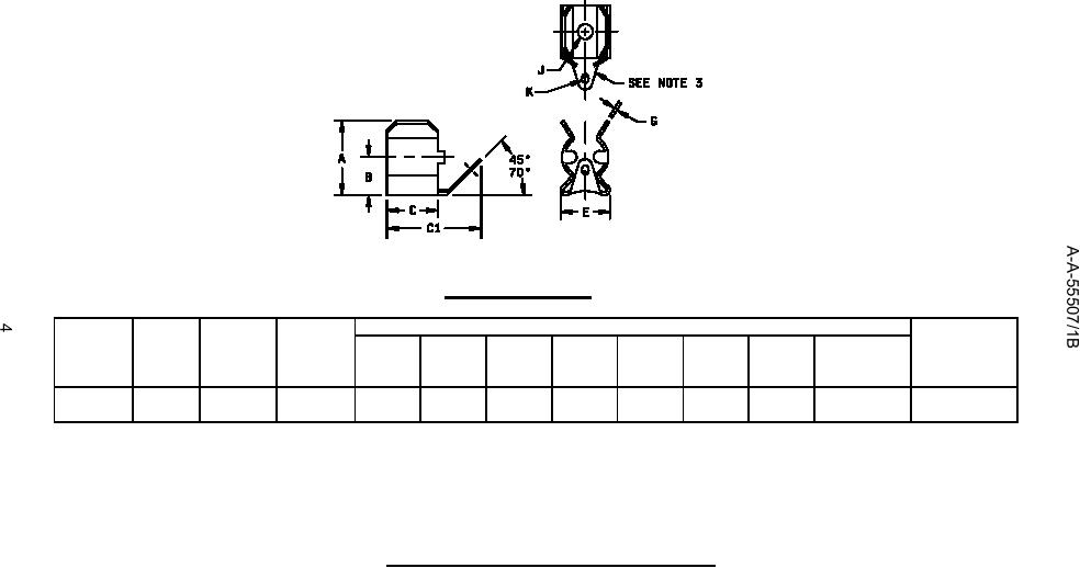
CONFIGURATION C
Dimensions (see notes)
Applicable
PIN
Material
Nominal
Maximum
fuse style per
AA55507/
fuse
current
A
B
C
C1
E
G
J
K
MIL-PRF-
01-
diameter
rating (A)
max
min
max
max
(dia)
15160
11
B
.250
30
.50
.23
.31
.60
.34
.020
.131
.09 x .16
F01, F02, F03
(6.35)
(12.7)
(5.8)
(7.9)
(15.2)
(8.6)
(0.51)
(3.33)
(2.29 x 4.06)
NOTES:
1.
Dimensions are in inches. Millimeters are in parentheses and are provided for general information only.
2.
Unless otherwise specified, tolerances are ±.02 (0.5 mm) for two place decimals and ±.005 (0.13 mm) for three place decimals.
3.
Solder lug terminal shall be formed integral with the fuse clip.
Figure 3. Configurations and dimensions, configuration C.
For Parts Inquires call Parts Hangar, Inc (727) 493-0744
© Copyright 2015 Integrated Publishing, Inc.
A Service Disabled Veteran Owned Small Business