INCH-POUND
MIL-PRF-83532/1B
7 June 2004
SUPERSEDING
MIL-PRF-83532/1A
30 December 1991
PERFORMANCE SPECIFICATION SHEET
DELAY LINES, 14-PIN DIP COMPATIBLE, 5 TAP
This specification is approved for use by all Departments
and Agencies of the Department of Defense.
The requirements for acquiring the product described herein
shall consist of this specification sheet and MIL-PRF-83532.
REQUIREMENTS:
Design and construction: Parts shall be of the design, construction, and physical dimensions specified in the
appendix of MIL-PRF-83532. Four case styles (A, B, C, and D) are available.
Input pulse: Delay lines must be capable of meeting applicable table I and table II requirements with an input pulse
having the following characteristics:
A: Leading edge of a positive-going pulse.
B: Minimum pulse width of 50 percent of total delay time.
C: Fixed pulse repetition rate equal to ten times the total delay time.
D: Duty cycle not to exceed 50 percent.
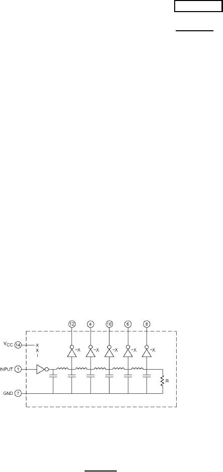
Schematic: See figure 1.
Delay times: Delay time from input to all taps shall be as specified in table I (+25°C) and table II (-55°C and
+125°C).
NOTES:
1. Schematic is for general information only.
2. Pins 2, 3, 5, 9, 11, and 13 are omitted on level A delay lines.
3. All pins are installed on level B delay lines.
FIGURE 1. Schematic.
AMSC N/A
FSC 5999
For Parts Inquires call Parts Hangar, Inc (727) 493-0744
© Copyright 2015 Integrated Publishing, Inc.
A Service Disabled Veteran Owned Small Business